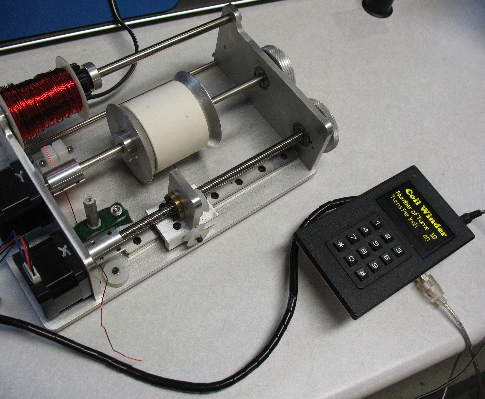
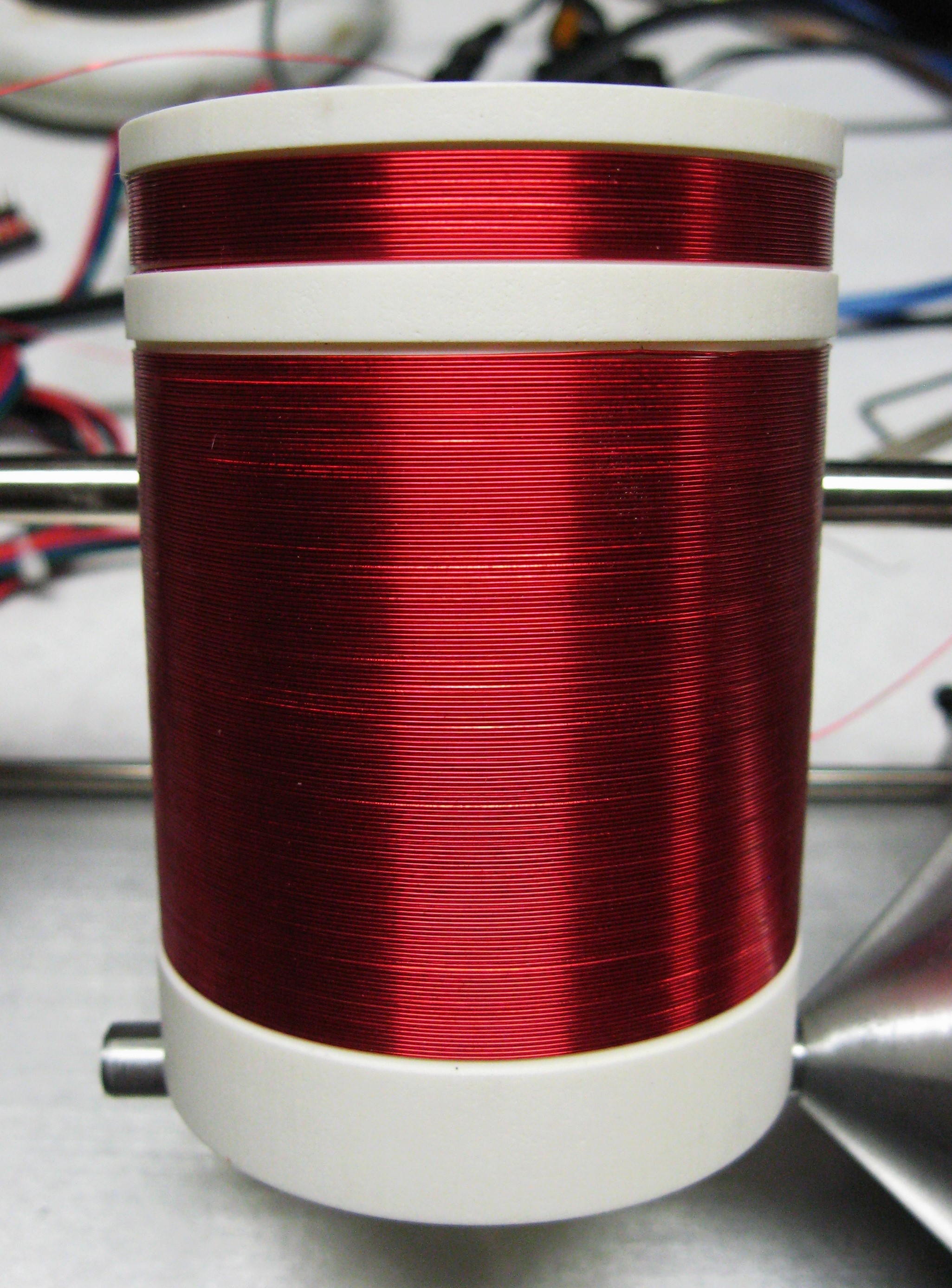
Coil winder made from scratch. Two Nema 17 stepper motors. One glide and one rail. 8 mm lead screw. Arduino Uno. Stepper Motor Shield and two motor controllers. Key Pad and Display. Home made PC Shield. 3D printed box.
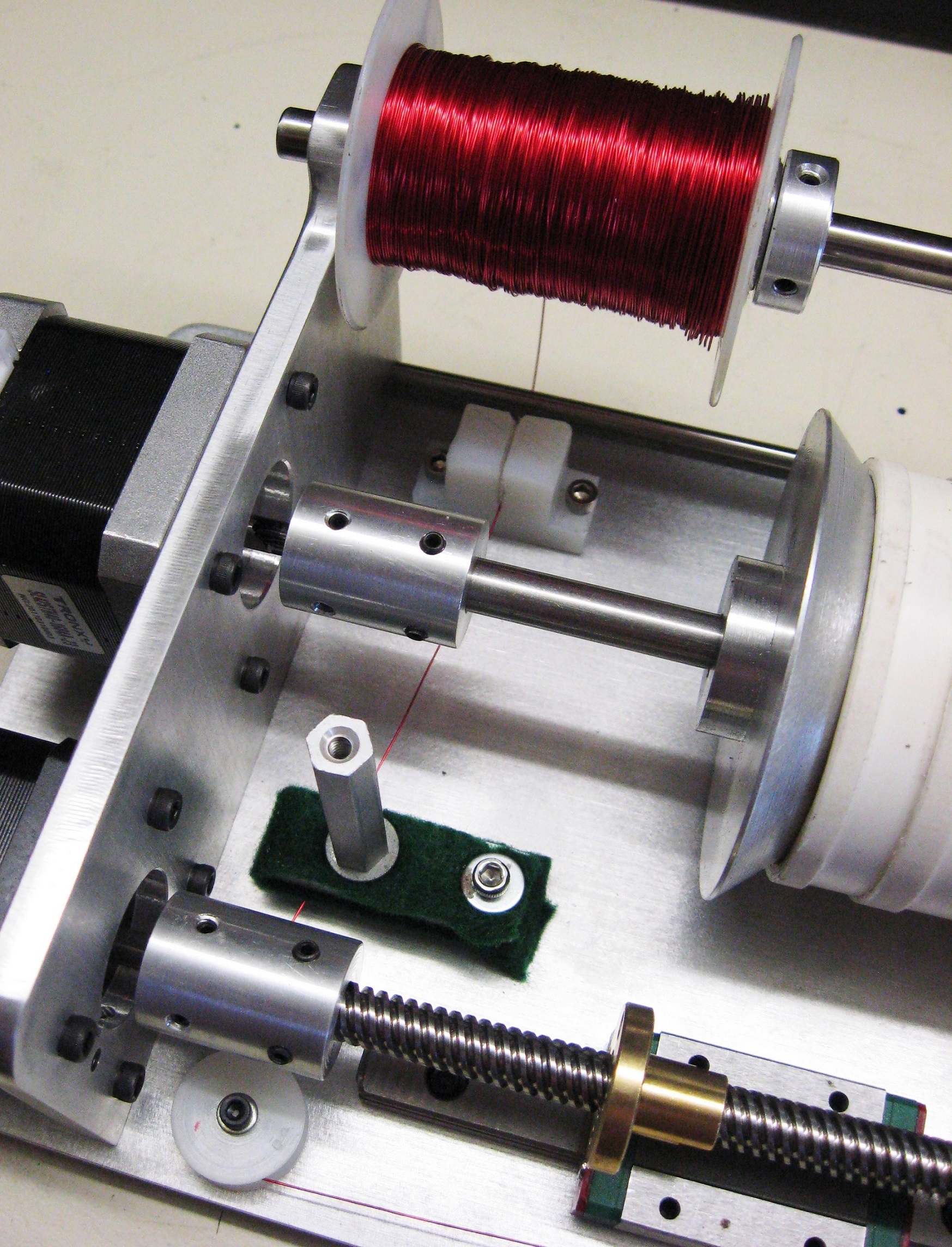
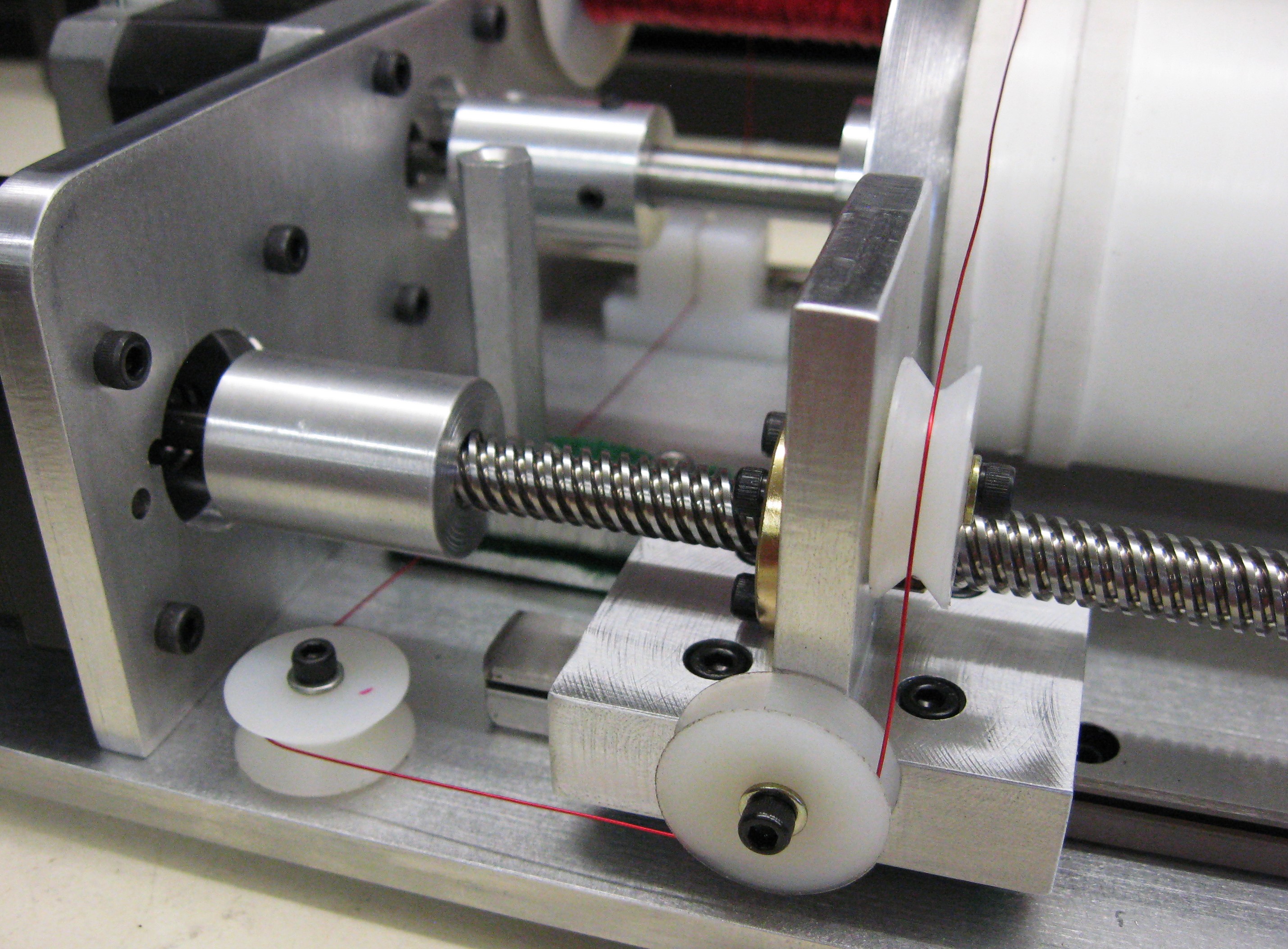
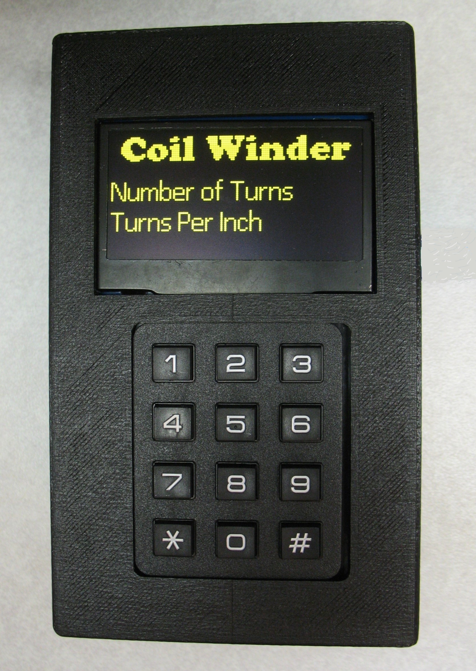
3D Printed Box is not perfect but it works.
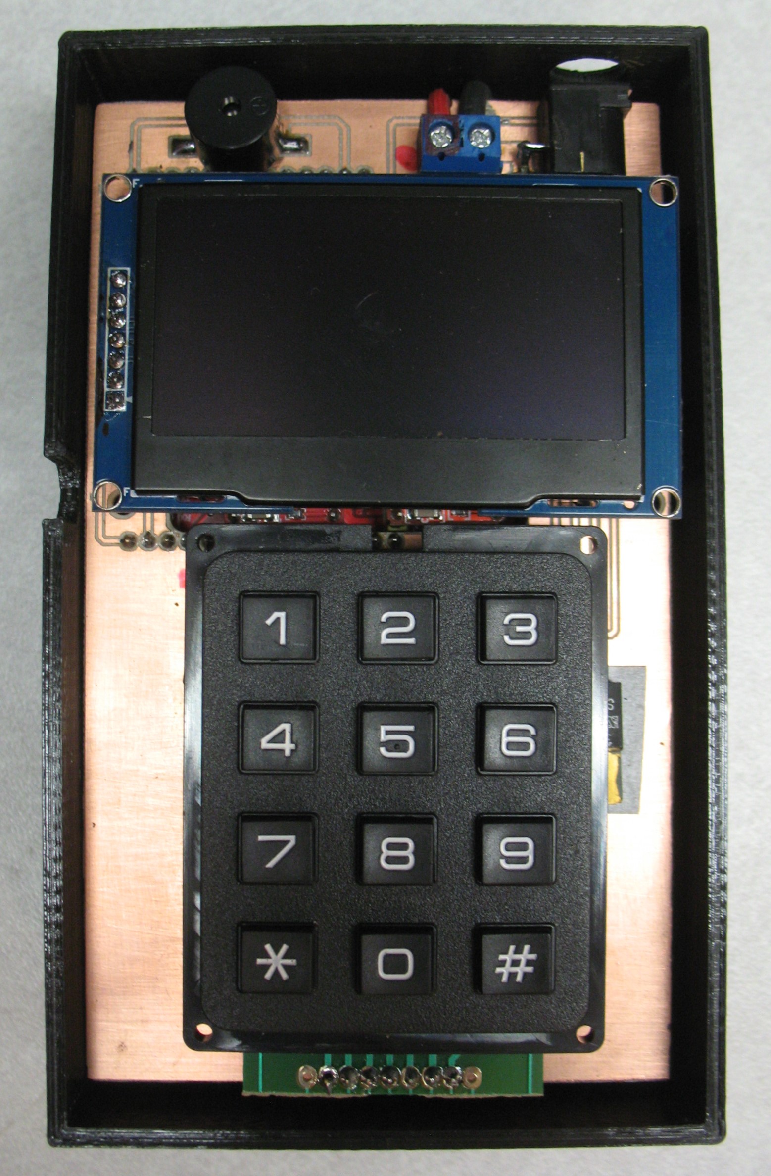
Key Pad and Display Plugged into Header Pins
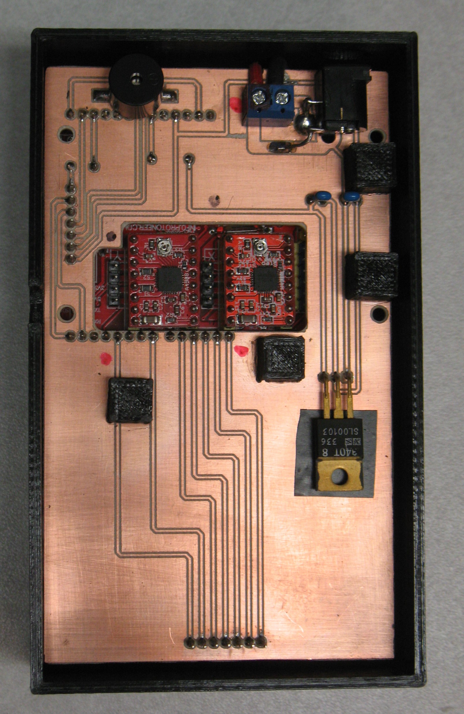
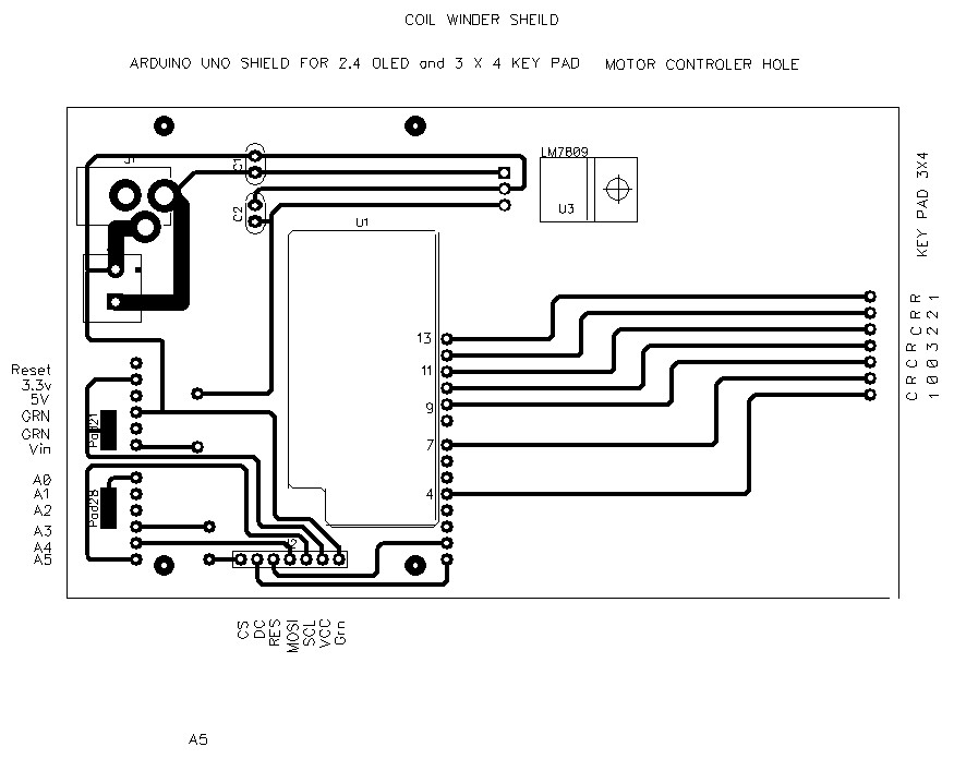
This Shield plugs into Motor Controller Shield. The Black cubes are printed support blocks. Regulator supplies Voltage from motor power supply to Arduino.
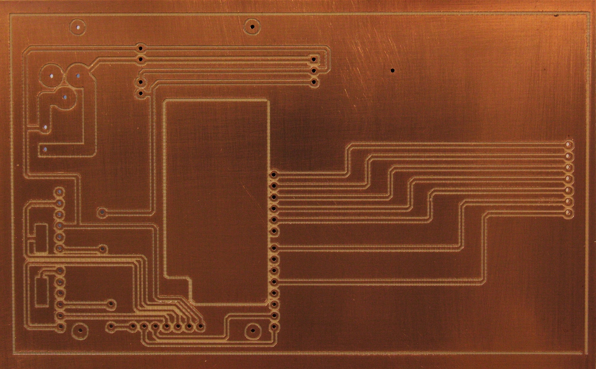
This PC board was made with my home maid PC Router. See it on this web site.
Just tell the controller How many turns you want and at what TPI and you have a coil!
The magic is in the code.
//Winder Shield OLED 2.4 Keypad 3x4 WA6OTP 1/12/2019 3:00 PM
#include <SPI.h>
#include "SSD1306Ascii.h"
#include "SSD1306AsciiSoftSpi.h"
#include <Keypad.h>
// pin definitions
#define CS_PIN A3
#define RST_PIN 1
#define DC_PIN 0
#define MOSI_PIN A4
#define CLK_PIN A5
SSD1306AsciiSoftSpi oled;
const byte ROWS = 4;
const byte COLS = 3;
char keys [ROWS] [COLS] = {
{'1', '2', '3'},
{'4', '5', '6'},
{'7', '8', '9'},
{'.', '0', '#'}
};
byte rowPins[ROWS] = { 7,13,12,10}; //Connect Rows to these Arduino pins
byte colPins[COLS] = { 9,4,11};
Keypad kpd = Keypad( makeKeymap(keys), rowPins, colPins, ROWS, COLS ); // Init Keypad
int outPin2 = 2; // digital pin 2 Step X
int outPin3 = 3; // digital pin 3 Step Y
int outPin5 = 5; // digital pin X Direction
int outPin6 = 6; // digital pin Y Direction
int nwt=0; // Number of wire turns
int pulses=0; // pulse start value
int tpi = 0; // Turns Per Inch
int revs=0; // unknown ?
float (tpidelay); // delay for timing
float (tt); // one turn time lead screw
float (pitch); // wire pitch
float (cl); // coil length
float (trns); // lead screw turns X axis
float (coiltime); // coil time
float(myentry); // Floating point variable for keyboard entry
void setup()
{
oled.begin(&Adafruit128x64, CS_PIN, DC_PIN, CLK_PIN, MOSI_PIN, RST_PIN); //SPI
oled.setFont(Cooper19);
oled.clear();
oled.setCursor(0,0);
oled.println(" Coil Winder");
oled.setFont(Callibri15);
oled.println("Number of Turns");
oled.setCursor(0,52);
oled.print("Turns Per Inch");
pinMode(outPin2, OUTPUT); // sets the digital pin 2 as output X
pinMode(outPin3, OUTPUT); // sets the digital pin 3 as output Y
pinMode(outPin5, OUTPUT); // sets the digital pin 5 as output X
pinMode(outPin6, OUTPUT); // sets the digital pin 6 as output Y
pinMode(8, OUTPUT); // enable motor on coltroller
digitalWrite(2, 0); //set pin 2 low X
digitalWrite(3, 0); //set pin 3 low Y
digitalWrite(5, 0); //set pin 5 High X direction
digitalWrite(6, 0); //set pin 6 High Y direction
digitalWrite(8, 0); //set pin 8 low Enable
}
void loop(){
ReadKeys();
{
nwt=myentry;
oled.setCursor(105,3);
oled.print(nwt);
}
ReadKeys();
{
tpi=myentry;
oled.setCursor(105,5);
oled.print(tpi);
coiltime=(nwt*1.63195); // 1 second / 489.950htz * 800 = time of 1 turns * number of turns, 490.21
pitch = (1.00/tpi); // pitch turn width
cl = (nwt * pitch); // coil length
trns = (cl /.318); // number of lead screw turns, #.318 = movement of caraige
revs=(trns*800); // one turn time of lead screw
tt=(coiltime/trns);
tpidelay=(tt/.80); // delay for timing * .8 insted of 800 toget decimal tocome out right
}
StartMotors(); // Start Motors
}
void StartMotors(){
analogWrite(3, 2); // Y motor 0n ,The duty cycle of "2" gives 16us pulse on 489.950 Hz
for (pulses = 0; pulses < revs; pulses ++) // X count pulse per revolution
{
digitalWrite(outPin2, 1); // X motor sets 2 pin HIGH
delayMicroseconds(10); // X pauses for 10 microseconds
digitalWrite(outPin2, 0); // X motor sets 2 pin LOW
delay(tpidelay); // X pauses for wire gauge
}
analogWrite(3, 0); // Y turn off (low) PWM Y motor
}